Have you ever thought about the accuracy of any of the environmental data you collect?
To take a specific example, how accurate is the vibration data you collect?
Surprisingly, we almost never ask this question.
After all, we spend good money purchasing that vibration monitor from a reliable manufacturer and it follows that the data it generates will be accurate. Won’t it?
And the answer is, yes – but only if you have set everything up properly.
But if everything was not set up properly, the data generated will be of questionable value.
Since data integrity is fundamental, it follows that if the data we are collecting is questionable, then everything we use that data for is compromised.
Getting it right is not difficult, but it does require attention to detail.
So, let’s start with the most common causes of questionable vibration data:
- The sensors are not mounted correctly
- The vibration monitor and/or the sensors are out of calibration
- The performance specifications of the vibration monitor and/or the sensors being used are inadequate for compliance/diagnostic purposes, or
- The monitor itself has not been configured appropriately.
This article will address the issues associated with sensor mountings.
The calibration of vibration monitors and sensors we have addressed in a previous article – Texcel Calibration Standards.
We will address performance specifications for vibration monitors in a future article.
We’ll address the sensor mounting issues from two perspectives:
- Blast monitoring – both compliance and diagnostic
- Monitoring in structures – for compliance, structural impact, or human exposure.
BLAST MONITORING
What sensors should we even be using?
All standards in this field refer to velocity levels (mm/s or in/s), so the appropriate sensor is the geophone and, normally, a tri-axial geophone array. The exception is for near-field diagnostic monitoring where a uni-axial geophone is more common.
While it is possible to use an accelerometer (acceleration is measured in mm/s2), the results need to be integrated to give velocity readings. While this is a fairly straight-forward calculation, it can become very inaccurate at low frequencies.
If we’re talking about compliance monitoring, what standards apply?
The most common references come from the Australian Standards (AS 2187.2-2006) and the International Society of Explosives Engineers (ISEE).
Is there a distinction between long-term and short-term monitoring?
- If your monitoring will be conducted long-term at the same location (say, at a mine site or a large construction project) you will be looking for consistency of data over time. In such cases it will be beneficial to prepare the sensor mounting location much more thoroughly than you would if you are only doing one-off measurements.
- On the other hand, if you are undertaking a one-off measurement at a sensitive location, you will probably have neither the time nor the necessary permissions to prepare an invasive sensor mounting.
Short-term blast monitoring
Where you should mount the sensors:
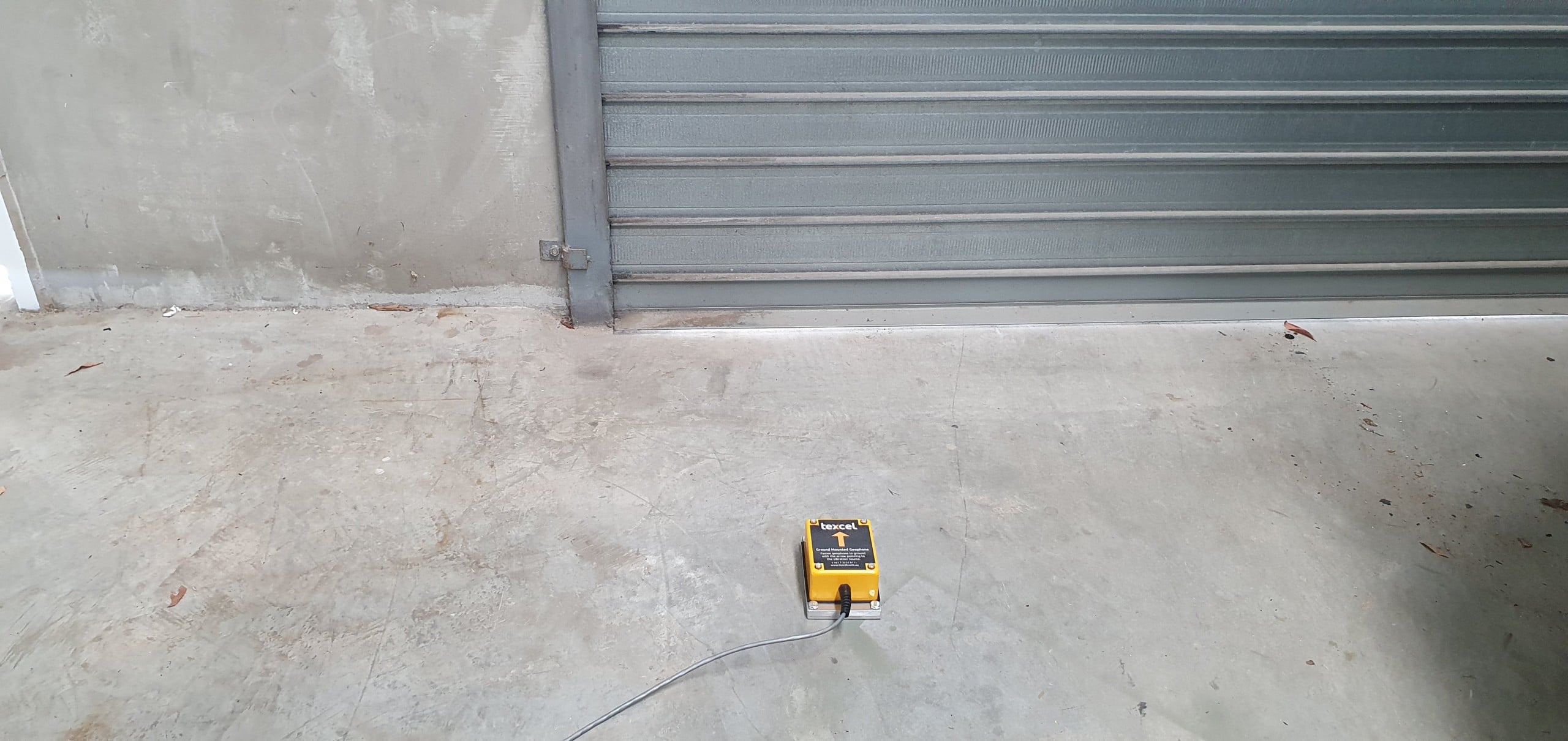
- If you are monitoring for compliance purposes, the vibration sensor should be mounted on or in the ground close to the structure or location of concern and facing the blast source.
- Driveways, footpaths, etc should be avoided since good contact with the ground will always be unknown.
- Mounting the sensor on the structure should also be avoided for compliance purposes as these readings will often be exaggerated by structural or model responses from the building.
- Ensure that the soil conditions are undisturbed or compacted fill. Avoid loose fill material, flower beds, etc.
- If you are monitoring for diagnostic purposes, the sensor should be mounted on the rock formation being blasted and close to the blast – typically 10 to 30m away.
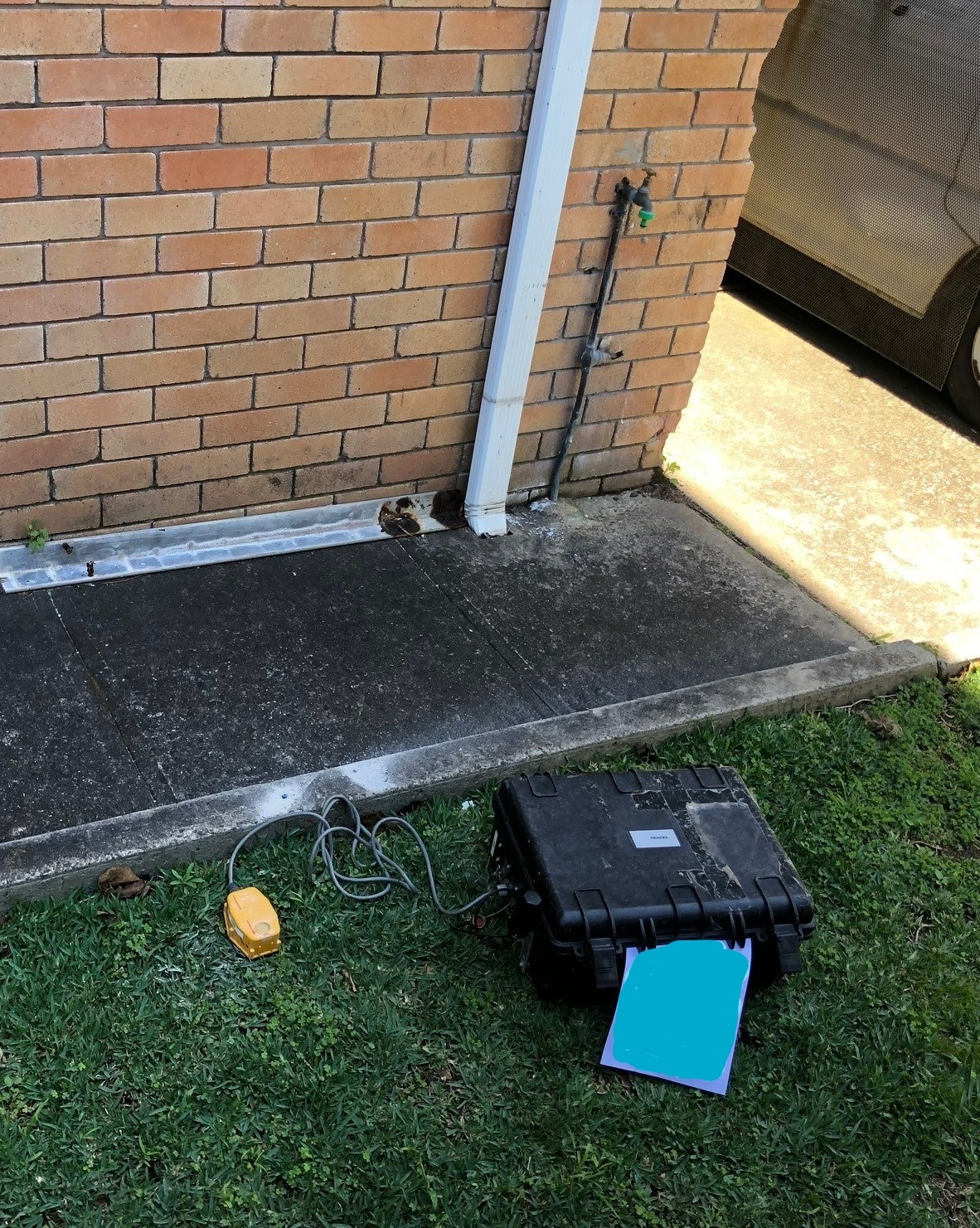
- If a microphone is to be used, it should be mounted on a tripod or similar stable device, close to the monitor, away from structures (which can reflect sound) and at least 1.2 -1.5m above ground level (this height requirement may vary between states/territories).
- Typically, diagnostic monitoring would not require a microphone.
How you should mount the sensors:
- Let’s start by stating what you shouldn’t do – simply place the sensor on the ground. This will distort the readings significantly.
- Placing a sandbag over the sensor, while marginally better, should also be avoided.
- Bonding the sensor to a suitable rock surface produces generally good results, but it is essential to pay close attention to ensuring the binding is tight.
- Anchoring the sensor (dyna bolt or similar) to a rock surface is even more effective. This is the mounting most commonly utilised for diagnostic monitoring.
- By far the most effective mounting utilises a concrete cube or cylinder that is carefully tamped into a specially dug hole. As this is generally not a viable option for short-term projects, further discussion on it is given below.
- For shear practical reasons, the most common technique is to attach soil spikes to the sensor case and push them into well-compacted soil – ensuring the spikes have been fully pushed in. A variation on this is to dig a hole, spike the sensor into the bottom of the hole, and compact soil over the unit. It must be stated, however, that while this methodology may be the only real option, the results will be neither as accurate nor as consistent and those generated by the bonded/anchored options given above. Note that this type of mounting should not be used for diagnostic monitoring.
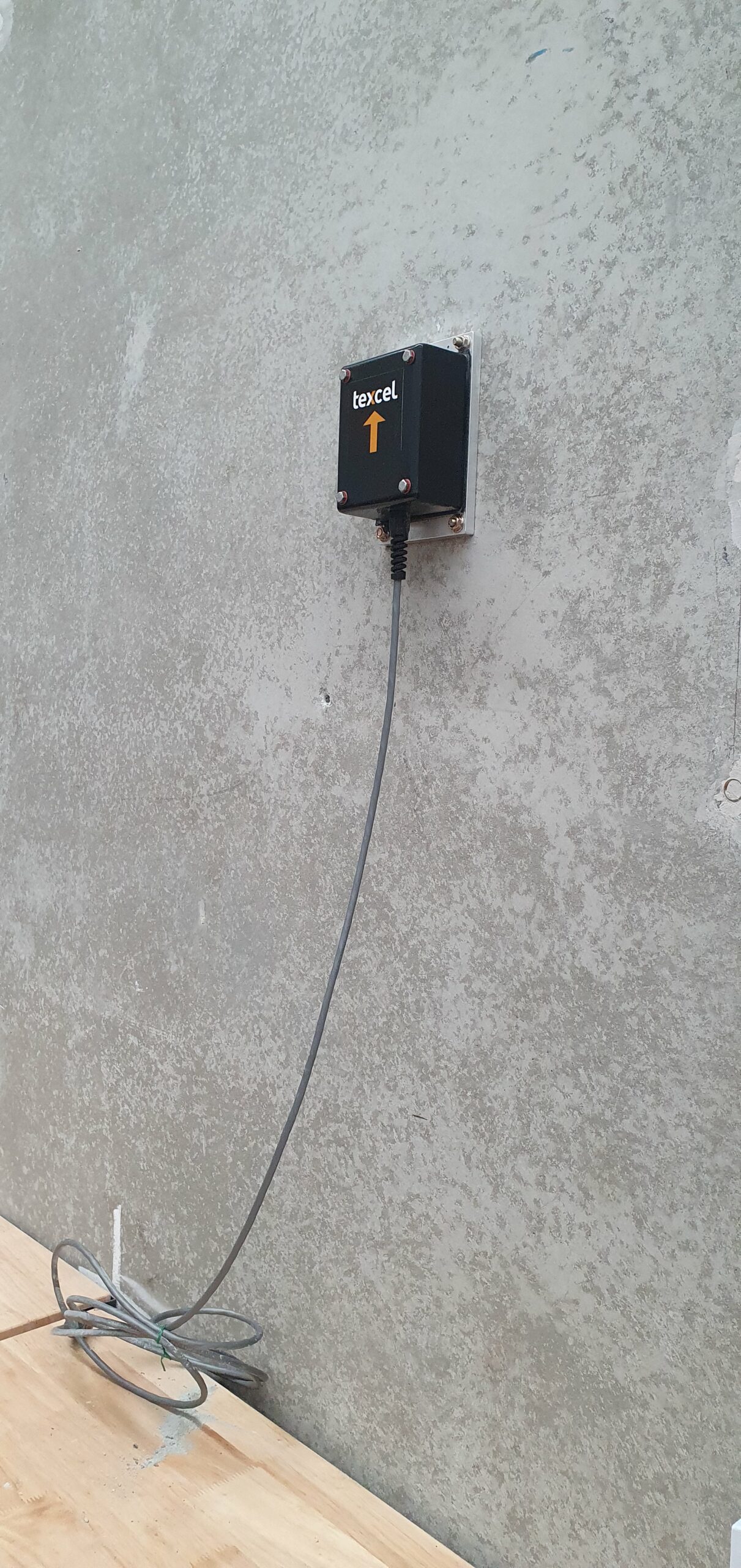
- In all cases, the mounting needs to ensure the sensor is horizontal (low frequency geophones are highly directional. In fact, if the unit is to be mounted on a vertical surface, you need to ensure a suitable vertical mount unit is utilised).
- The sensors used for diagnostic monitoring are omni-directional (although they will not work upsidedown), so this requirement does not apply.
- While not critical, the arrow on the sensor case should be oriented towards the vibration source.
- If used, the microphone should always be used with its windshield. The orientation is not critical, but if possible, it should be directed towards the noise source.
Long-term blast monitoring
Where you should mount the sensors:
- The same general rules shown under short-term monitoring also apply here.
- Often, however, operational considerations may determine where you locate the sensors – e.g. proximity to power supplies (solar or mains) may be critical. Security concerns may also be important.
How you should mount the sensors:
- Since in these long-term projects, not only data integrity, but also on-going data integrity, is fundamental, we will only discuss here the optimal mounting technique.
- This is where the sensor is bonded/anchored to a concrete cube or cylinder that has been embedded in a specially dug hole.
- Please be aware that there is at least one technical paper on how to correctly calculate the optimal size of the cube/cylinder – e.g. the Dane Blair paper in Geophysics from January-February 1995 titled “Soil-embedded detector mounts for seismic monitoring”.
- A very pragmatic summary of this paper would be:
- Pre-prepare a 200 mm concrete cube (or similar sized cylinder). Do not pour the concrete directly into a hole, since as it cures, it will partially de-bond from the soil.
- Dig a hole to fully enclose the cube while allowing space to carefully compact soil around it.
- The sensor case is anchored (or glued, if done carefully) to the top of the cube.
- This technique will produce consistent results over the long term.
- If a microphone is to be used, the same general rules given above still apply, except it would be mounted on a permanently mounted pole rather than a tripod.
MONITORING FOR STRUCTURAL IMPACT OR HUMAN EXPOSURE
What sensors should we be using?
Where prescribed levels are being imposed, be guided by the standard you will be held to – this will usually be a velocity standard (i.e. geophones should be used), but it could be acceleration (i.e. accelerometers should be used).
Where the engineers are wanting to investigate the structural impact of the vibration, they will usually want to see acceleration values (i.e. an accelerometer should be used).
If you are measuring for human impact (VDV), tri-axial accelerometers are the usual sensor.
What standards apply?
The most common references come from the German Standards (DIN 4150-2E: 1999 deals with human response and DIN 4150-3E: 1986 deals with structural impact) and the British Standards (BS 7385-1: 1990 and BS 7385-2: 1993 deal with structural impact and BS6472-1: 2008 and BS 6472-2: 2008 deal with human response).
Because all buildings differ in age, design and construction methodologies, it may be beneficial to contract a suitably qualified structural/geotechnical engineer to advise where and how you should monitor.
Where you should mount the sensors:
For structural impact, the preferred location is at the foundation – e.g. a point low on the main load-bearing external wall at ground level.
It should be noted that vibration levels may be amplified within the building in proportion to the height of the building. This means that it may be necessary to carry out simultaneous measurements at several points within the building.
A rough guide would be where a building is higher than 4 floors, additional measuring points should be added every 4 floors and at the highest floor in the building. Where the building is more than 10m long, additional horizontal measurement points may be necessary. Response from residents may also require the addition of measurement points.
The standard measure of the impact of vibration on humans is VDV (Vibration Dose Value). When measuring VDV, the sensor should be mounted on the floor close to where the people being impacted work.
How you should mount the sensors:
Where possible the sensors should be mounted on a hard surface as opposed to soft surfaces such as carpets. This is because the sensor is unlikely to be well coupled to the floor when carpets come between them.
In most cases the sensors should be bonded to the hard surface, but an appropriate double-sided tape can be used where bonding is not possible.
Orientation of the sensor is usually not critical in these situations.
When it comes to data integrity, remember:
Because data integrity is a fundamental input for your project, care and attention to how and where you mount sensors is critical.
If in doubt about any of the issues discussed above or if you simply want to discuss your options, please feel free to contact Texcel at any time.